

The new Volvo Ocean 65 may be one-design but no stone is being left unturned to ensure that maximum reliability is delivered with maximum performance. Farr Yacht Design’s Alon Finkelstein looks in detail at VO65 appendage design
In keeping with the conceptual philosophy of the rest of the yacht, the design brief for the VO65 required the appendage package to be significantly less costly than that of a Volvo Open 70 (VO70), with equivalent or higher safety factors… and a similar performance envelope. Although at the outset this seemed like a tall order, without the rigid constraints of the previous VO70 rule we found numerous fruitful areas to explore that delivered excellent return on investment in terms of performance improvements without additional cost or reduced robustness.
Keel
The VO65 keel fin is machined from a solid steel forging and is designed to comply with all of the stringent structural requirements of the previous VO70 rule. In addition, the fin meets or exceeds all the requirements of Germanischer Lloyd’s (GL) new Guidelines for the Structural Design of Racing Yachts over 24m including keel torsional strength and a complete fatigue assessment.
After reviewing the proposed stopover ports for the 2014-2015 edition of the Volvo Ocean Race, the organisers decided that an increase in maximum draft from 4.5m to 4.7m would be acceptable. This extra 200mm of draft allowed us to increase righting moment without increasing keel weight, giving the boat a noticeable performance improvement without incurring any significant extra cost.
The previous VO70 rule required the keel pin axis to be parallel to the waterline. This resulted in very low and sometimes negative sideforce loading on the keel fin. Negative sideforce is undesirable because it pushes the yacht to leeward thereby increasing leeway angles. Negative keel fin sideforce also comes with an induced drag penalty. From our very first Imoca 60 designs we’ve known that there was value in adding some incline to the keel pin angle, to ensure that the keel fin would produce positive sideforce under all points of sail. Recent high-performance cantingkeel ocean-racing yachts have pursued relatively large keel pin axis incline angles of as much as 8°.
An inclined keel pin axis has a number of positive effects on performance. First, it creates a large vertical lift force on the keel fin which reduces the effective displacement of the yacht, which in turn reduces the wetted surface and drag of the entire yacht system. Second, even when canted and heeled, the keel fin creates a positive side force which reduces leeway angle. This is a significant factor for high beam to draft hull forms such as this one, because they present a very asymmetric shape to the water as they heel. As leeway is reduced the amount of asymmetry also reduces, providing a substantial associated reduction in form and residuary resistance.
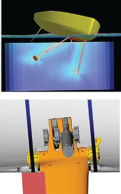
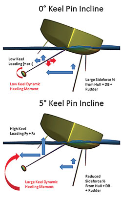 Above: halyards are used to lift the daggerboards on the new VO65, removing the complexity of dedicated lift struts. The effect of keel pin inclination on appendage forces is shown in two diagrams.
Below: This Fine/Marine simulation shows VO65 appendage vorticity. Inclined keel pin installation is seen here (bottom).
Operating at low or negative leeway angles also has the advantage of effectively increasing the sail sheeting angles which further improves the aerodynamic efficiency of the yacht. All of these are positive performance factors; however, they are countered by the large heeling moment generated by the additional loading on the keel which in turn must be overcome by depowering of the sails, or by increasing bulb weight. The trade-offs are quite complex and often very subtle, and they need to be assessed in the context of dynamic trim of the yacht at speed and in the expected racing conditions.
Given the complex trade-offs, and the implications on helm load and balance that result from changing the load sharing between hull, keel, daggerboard and rudder, we felt it was important to complete a very detailed study of these effects.
Our detailed research used NUMECA’s Fine/Marine RANS flow solver running on FYD’s high-performance computing cluster to simulate the hydrodynamics in selected operating conditions. The data was then incorporated into hydrodynamic response surfaces using a radial basis function technique developed internally at FYD. Our studies used a VPP methodology where we balance aerodynamic and hydrodynamic force and moment response surfaces that are a function of speed, heel, yaw, daggerboard depth, and rudder angle.
Balancing this hydrodynamic data set with wind tunnel-derived aerodynamics models allowed us to refine our understanding of the interplay of these tradeoffs. We also leveraged this data to refine our daggerboard positioning, toe-in angle and section size.
As expected, the choice of keel pin axis incline angle has a powerful impact on yacht performance, with the vertical force generated by the keel substantially reducing the overall drag of the yacht, especially at high speed. However, the impact of the hydrodynamic heeling moment from the keel cannot be ignored and does result in depowering at lower wind speeds.
The performance advantage is most pronounced when sailing in fully powered conditions and degrades rapidly as you approach the depowering capacity of any sail combination. Our work supported a keel pin incline angle of 5° as being optimal for a typical Volvo Ocean Race course. By inclining the keel pin axis the VO65 should be capable of similar speeds to a VO70 in certain conditions, even though the boat is 5ft shorter, heavier for its size and has a lower righting moment.
Bulb
The bulb shape is relatively long with a generous amount of ‘squish’ (the ratio of bulb width to height). A high squish ratio helps lower the centre of gravity and increase stability, the downside being an increase in wetted surface area. The squished bulb sections are blended into a flat tail at the trailing edge which helps increase the effective span of the keel fin.
Canting-keel system
The canting-keel system utilises two opposing hydraulic rams, and is very similar to the style of system used successfully on the VO70s. As with the VO70, the system has been designed to operate safely with only one ram to ensure complete redundancy. FYD worked closely with the hydraulic experts at Cariboni in Italy to ensure that the geometry of the canting system resulted in a concept that is light and with a low centre of gravity, while still being relatively simple and inexpensive to produce. Hydraulic supply ports were also located in such a way as to be sympathetic to the needs of the sailors onboard, with good access and visibility.
Daggerboard
Our initial concept work considered a single rotating and retracting centreline daggerboard, the goal of this daggerboard arrangement being the reduced demand on a small crew having to repeatedly tack asymmetric daggerboards, particularly during the in-port races. However, after assessing the results of cost input from Green Marine and the sailors’ desire for a more conventional arrangement, the twin daggerboard option was selected instead.
To minimise the need for spares the daggerboards are both fully reversible and therefore interchangeable. Unlike on many of the VO70s, the upper daggerboard bearing is supported at the deck which adds length and weight to the daggerboards. Although lowering the upper bearing support midway between the hull and deck theoretically results in a lighter overall structure, the builders’ consortium felt that this would add an undesirable level of construction cost and assembly complexity.
The daggerboard incline angle has been chosen to allow them to be lifted by halyards directly from the mast, avoiding the complexity and maintenance requirements of retractable lifting struts. There are certainly performance benefits associated with more vertical or even negative incline angles on the daggerboards, as featured on many recent contemporary high-performance canting-keel ocean-racing yachts; however, a negative daggerboard incline angle would require retractable lifting struts. The feedback from the shore teams and boat captains was that lifting struts get frequently damaged and consume a lot of time, money and effort to maintain, so they decided these downsides outweighed the performance benefits.
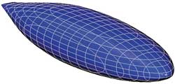 Above: the finalised VO65 bulb shape.
We also considered several styles of roller bearings, popular on other boats where friction minimisation is critical. However, these bearings were eventually rejected in favour of more cost-effective, simpler bearing assemblies. The daggerboard bearings are machined plastic blocks that are self-aligning with the deflected shape to reduce friction.
The daggerboard foil section was chosen to provide good lift-to-drag ratios in the wide range of conditions we expect they will operate in. The foil section chosen has a relatively round leading edge giving it a wide groove, which should make it forgiving and tolerant of any large angle of attack variations caused by waves, dynamics and changes of course.
Rudder
The potential for rudder failure is always a significant concern and some of our original concepts considered the use of an Imoca 60-style kick-up rudder system to provide additional reliability. After discussion with a consortium of sailors and builders, the kick-up system was abandoned due to cost and complexity, and a more conventional rudder installation selected. To be as robust as possible the rudder blade and stock laminates are designed to meet the most onerous of ISO, GL and FYD’s own design criteria. Each VO65 will carry a spare rudder identical to the two primary rudders. In the event of a rudder failure the spare can be installed back into the original bearings while underway or installed in a transom-hung emergency cassette.
Conclusion
It is never easy trying to balance the often competing desires of the sailors, shore crew, designers, builders’ consortium and race organisers. When we developed the appendage package for the new VO65 we had input from all these groups, plus the mandate to reduce cost and improve structural reliability… and maintain a level of speed and performance commensurate with the image of the world’s toughest ocean race. With the various developments we have made in each department we believe that we have succeeded as a team in achieving the project goals.
We invite you to read on and find out for yourself why Seahorse is the most highly-rated source in the world for anyone who is serious about their racing.
To read on simply SIGN up NOW
Take advantage of our very best subscription offer or order a single copy of this issue of Seahorse.
Online at:
www.seahorse.co.uk/shop and use the code TECH20
Or for iPad simply download the Seahorse App at the iTunes store