


The first of the new Carkeek CF520s 52-foot IRC racers is now taking shape at Fibre Mechanics’ Lymington yard, with the structure of boat one nearing completion. You may wonder why a boatyard would choose the name ‘Fibre Mechanics’... Well here’s a clue
Building a racing yacht today is a very different experience from how it was 25 years ago and it’s not just due to advances in materials. In fact, the basic materials and techniques have hardly changed. The resins are tougher, the carbon is stiffer, and the honeycomb is now made of Kevlar not Nomex. But compared with the materials revolution that took place between 1980 and 1995 you’d have to say that the development of race yacht building materials has plateaued.
Nonetheless, things are very different now for two reasons. First, developments of the 1980s and 90s left us with materials that have more predictable properties, and this allows composite engineers to design far more sophisticated structures. The laminate ply books we work with today are a great deal more complex, precise and optimised; and since materials properties are more reliable, engineering safety factors can be reduced.
Second, non-destructive test apparatus and techniques have improved greatly and become far more available to the marine industry. And alongside that evolution there are some highly experienced operators specialising in yacht structures, who can give very reliable information about a laminate or a structural bond quality.
Both of these are major advances, but from a builder’s perspective more optimised laminates allow less room for error; and better NDT means that errors are more likely to be detected. Taking both together, we are left with a set of technical issues to resolve and also some issues of engineering philosophy to wrestle with. We’ll look at the philosophy first, and if you’re still with us after that we’ll look at some of the technical issues…
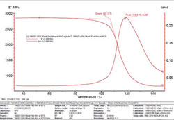
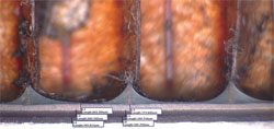 Above: this is a microscopy image of the bond between a carbon skin and Nomex honeycomb core. The vertical stripes are the cell walls of the Nomex honeycomb, and the distance between each cell wall is 3.2mm. We want to see the quality of the resin fillets that form between the Nomex cell walls and the laminate skin. Ideally we like to see fillets that are completely clear of any air bubbles, that are full fillets as opposed to shallow indentations in the adhesive film, and that extend up (or down) the cell walls as required. We can vary the fillet size by changing the amount of adhesive used, or by fine-tuning the cure schedules, and also by changing the way in which the adhesive itself is applied
Whose fault is it anyway?
Architects and engineers design boat structures to withstand loads agreed with the owner. Though in deciding what those loads should be, most owners will put the question back to the engineer. At the design stage the owner will ask for the lightest solution possible, and in most cases engineers will rely on one or other classification authority or standard (CE, DNV/GL, ISO and so on) to set the appropriate strength level.
Once sailing, it is the owner’s responsibility to make sure the boat operates within the limits agreed, though exactly how sailors should recognise the point at which a boat is being overloaded is another matter (on which we have views…).
Bearing all that in mind, who is to blame when a boat breaks?
- Did the owner overload the boat?
- Were the maximum loads assumed by the engineer too low?
- Did the designer make a calculation error?
- Was the builder issued with drawings that reflect the engineer’s calculations?
- Was there a critical flaw in the composite laminates?
It is hard to quantify what actual loads were applied at the point of failure unless the boat has instrumentation designed to do that job onboard, so the owner will typically look to the builder and engineer for answers. Barring errors, the engineers can usually demonstrate that a composite laminate meets the design brief. And the classification authorities who set the brief do not warrant that their scantlings are adequate for specific boats, they can only confirm that specific designs meet their standards…
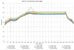
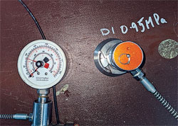 Skin-to-honeycomb core bond testing. To check the strength of the bond between a carbon skin and honeycomb core we pull a small disc of laminate directly off the core with a hydraulic pull-out tester (above). First we cut through the skin with a hole saw, then attach the test rig to the laminate skin. The test rig measures the force required to separate the skin from the honeycomb. The first thing we look for is that the bond is stronger than the core; then we look at the size and quality of the fillets formed between the two
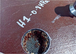
All of which leaves the builder in a weak position because, in stark contrast to the position of the designer, owner and class authority, it’s very easy to identify minor flaws in practically any laminate, leaving the builder trying to argue that, for example, the porosity in a laminate is at such a low level that it should not have caused the boat to break.
And that is why building boats today is so different. As builders we need to go about the business of building yachts in such a way as to eliminate errors and avoid pitfalls at every stage. There are a number of strategies that we employ to do that.
First, where practical, we prefer to take responsibility for the structural engineering. We often use the same specialist engineers whom the naval architect consulted at concept stage – but the engineers work for us as builder and take account of the materials and techniques that we have developed. Where that is not an option we employ a third party engineer to doublecheck the drawings and verify the calculations behind them for key areas of every boat we build. There have been at least three occasions when we did not do this, and we lived to regret each one.
Second, we apply commonsense and experience and reject structures or laminates that we don’t like; there are about a dozen common details that we will always reject or modify. For example, we never accept 300g cloth as the first ply into a hull mould because the overlaps are too thick and the unidirectional fibres that run over the top form a void at the edge of the cloth overlap.
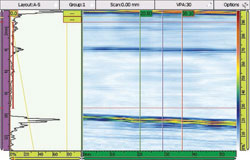
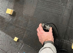 Above: phased array ultrasound inspection. An area of single skin pre-preg carbon is scanned by sliding an ultrasonic phased array probe over the inner surface. The scans are monitored during the inspection and are also recorded to be examined later. Water has been spread across the laminate surface to ensure a good connection with the probe. To interpret the signals generated requires a detailed knowledge of the structure that is being examined. Put another way, in the hands of specialist surveyors like Ben Pierrepont (Pierrepont Analysis) or Stefano Beltrando (QI Composites) you can learn more about a laminate than a raw ultrasound probe should be capable of detecting. Typically during a composite ultrasound inspection we are looking for:
- Voids: air inclusion between layers and/or between core panels
- Delamination: total debonding between adjacent layers
- Disbond: a lack of bond between two substrates, most typically a composite skin to core disbond in a sandwich panel
- Blisters: delamination with deflection of one layer
- Porosity: many small voids present between or within the layers
- Inclusions: foreign material that is not specified in the laminate schedule
- Cracks: fibre interruption or other categories and types of discontinuity
Third, we can agree a non-destructive test criterion that sets out the level of porosity or size of void that is acceptable at the start of a project so that we can use non-destructive test methods to assess the laminates we build against the agreed standards.
Fourth, while building a boat we can address all the technical issues that we know cause laminate defects. Which brings us to the next section of this piece: in ways that are often far from obvious, apparently small evolutions in boatbuilding technique have improved the quality of the laminates and joints that make up the structure of a racing yacht in 2021.
A racing boat structure is just a stack of carbon, resin and foam or honeycomb core…
But if you put these three ingredients together in the wrong way or in the wrong combination there are far more than three things that can go wrong.
When we are evaluating a laminate or structure the main things we are looking at are the correct ratio of fibre to resin, air voids in the laminate, laminate porosity, fibre wrinkling, contamination, state of resin cure, honeycomb fillet size, skin debonding or blistering, core bridging over laminate overlaps. And we look for these at three levels.
First level inspection is visual. Some of our most experienced team leaders have been building boats for decades; it’s surprising what an experienced composite boatbuilder or laminator can pick up. A visual inspection is a much underestimated first line of defence.
Second level inspection uses nondestructive techniques. There are many pieces of NDE technology available: ultrasonic transducer inspection, core bond testers, laser shearography, thermal imaging etc, and in the right hands each of these has its place. The best surveyors have years of experience with boat structures, they know what the engineer requires and they know how the laminate was built. As with visual inspection, the best practi - tioners can tell you more about the laminate than you’d think possible.
Ultrasound is mainly used to find voids and to characterise the porosity level of a laminate, though it is generally only practical to test large areas by grid sampling points 100mm or 200mm apart. By using a dual-element ultrasonic probe, the bond between skin and core can be inspected, though many would argue that laser shearography is a better method for this. An experienced ‘shearographer’ can detect voids and dis-bonds deep in a laminate, even between layers of core material.
A thermal camera can inspect a large structure in a short space of time, but only in a superficial way so it is often used in conjunction with ultrasound – a coarse and fine approach. The thermal camera has some unique strengths, however: for example, it can pick out air voids within a tight resin fillet and, because it is not just point sampling, it can identify areas of dry laminate where the vacuum has removed too much resin during cure.
Third level inspection is destructive testing. We build test panels alongside all main components so that we can do mechanical testing on a test piece that was made with the same material batches and has been cured with the same cure schedules. We’ll send resin samples back to the lab to check for state of cure; we’ll check the bond between skin and core with a pull-out test apparatus; we’ll measure fillet size on honeycomb and air inclusions in adhesive film.
Destructive and Non-destructive testing tells us more about a laminate than ever before, and this has enabled builders to develop techniques to reduce potentially fatal flaws
At this point we could delve into the detailed QA procedures all boatyards now employ, but there’s no space for that in this article so we’ll focus on build procedures. There are dozens of ways in which a laminate can be degraded and a builder must have a strategy to counter each one. Fibres must run straight; resin ratios must be within a given band; resin must be sufficiently cured; honeycomb fillets must be consistent and sufficiently large, etc. Here are three examples of the steps we take to build better laminates…
1. Environmental controls
It can take a number of weeks to laminate the skin of a large yacht. For a boat made from unidirectional carbon in particular, it is vital to keep humidity at a constant level, and the longer the length of boat we are laminating, the more important it becomes. Uncured epoxy resin is prone to absorb water; if we let the humidity rise overnight (by letting the temperature fall, for example), the resin will absorb water and the laminate will try to expand.
We use large quantities of unidirectional pre-preg and a good proportion of the fibre runs the full length of the boat. It only has to lengthen by a fraction of a millimetre for the fibre to try to move out of column. The site at which this happens will be the point at which the fibre bridges a ply overlap. We mentioned earlier that we won’t use heavy cloth as a first ply in a hull mould, and this is the reason. If a ply overlap or drop-off is too big and/or the humidity is allowed to deviate too much, the fibre will form a wrinkle overnight. Few things upset structural engineers more than a wrinkle in unidirectional fibre.
2. Resin flow during cure
It is simple enough to control the humidity in a small oven or autoclave, but the situation is different in a large hull oven that is 40m or 50m long and 5m high. Also there will usually be a difference between the temperature of the air in an oven and the mould tool surface. It’s up to the builder to control the temperatures in every part of the oven in order to achieve the best overall laminate.
We are not just talking about curing the resin – that happens anyway in the final 10-hour ‘cook’. The quality of the laminate is determined during the period that the oven temperature is rising – ramp rates and dwells determine air release, resin bleed and honeycomb fillet size.
At room temperature the resin is a solid and dry to the touch; at 35° it is a sticky liquid; at 65° it is a liquid with the viscosity of water; at 75° the chemical reaction is starting to take hold, but the resin remains mobile for several hours before it ‘gels’.
If we get too much ‘flow’ we will remove too much resin from the laminate, resulting in areas where the laminate has a large number of very small voids (porosity). Too little flow and we degrade the bond between the plys of materials and trap larger air voids in the laminate.
For honeycomb bonding operations the size of the fillets between skin and core are in part determined by the time the resin is allowed to flow. All raceboat yards will have developed a series of cure schedules for different resin systems and laminate types, in our case these have been perfected over many years by trial and error.
3. De-bulking
The carbon fibre that we use here is pre-impregnated with uncured epoxy resin and stored in a freezer to prevent it curing. At room temperature the resin is workable for between 30 and 50 days, depending on exactly what temperatures it has seen before freezing and during transport.
Completing the laminate of a complex inner or outer skin for a large yacht can take three or four weeks, so some of the material will be close to the end of its workable life out of the freezer before the hull is cooked. As time goes by the tack and flow characteristics of the resin will change, and the tendency to trap air between plys of carbon increases.
Experienced laminators know how to deal with this, partly by altering the method of laying down the materials and partly by small adjustments to the oven temperature. Very small adjustments, that is. Too hot and the resin turns tacky and you trap air. Too cold and you risk humidity and/or tooling shrinkage.
Good technique helps, but trapping a small amount of air between plys is inevitable so we need to de-bulk laminate frequently by applying a vacuum bag to reduce air inclusion to a minimum. Debulk techniques have evolved significantly and the frequency of de-bulking has also changed. We now recognise that trying to pull air up through a laminate of more than 150g/m2 is not effective, so it has been important to find efficient methods to de-bulk almost every ply of laminate.
The extreme care with which modern raceboats are built bears a closer resemblance to work carried out in an aircraft factory than to most people’s idea of working in a boatyard.
By engaging with the latest NDE techniques we have been able to fine-tune the details of all our build processes, so that with good technique and careful control we can produce excellent carbon composite structures at a fraction of the budget that is typically available in the aerospace industry.
Geoff Stock, Fibre Mechanics
Click here for more information on Fibre Mechanics »
We invite you to read on and find out for yourself why Seahorse is the most highly-rated source in the world for anyone who is serious about their racing.
To read on simply SIGN up NOW
Take advantage of our very best subscription offer or order a single copy of this issue of Seahorse.
Online at:
www.seahorse.co.uk/shop and use the code TECH20
Or for iPad simply download the Seahorse App at the iTunes store